7805 voltage regulator. Voltage regulator
Voltage stabilizer is the most important radio element of modern radios electronic devices. It provides a constant voltage at the output of the circuit, which is almost independent of the load.
Stabilizers of the LM family
In our article we will look at voltage stabilizers of the LM78XX family. The 78XX series is produced in metal cases TO-3 (left) and in plastic cases TO-220 (right). Such stabilizers have three terminals: input, ground (common) and output.


Instead of “XX”, manufacturers indicate the stabilization voltage that this stabilizer will give us. For example, a 7805 stabilizer will produce 5 Volts at the output, 7812 will produce 12 Volts, and 7815 will produce 15 Volts. Everything is very simple.
Connection diagram
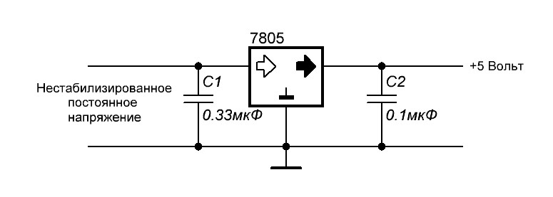
And here is the connection diagram for such stabilizers. This circuit is suitable for all stabilizers of the 78XX family.
Characteristics of LM stabilizers
What voltage should be supplied for the stabilizer to work as it should? To do this, we are looking for a datasheet for stabilizers and studying it carefully.We are interested in these characteristics:
Output voltage – output voltage
Input voltage- input voltage
We are looking for our 7805. It gives us an output voltage of 5 Volts. Manufacturers noted a voltage of 10 volts as the desired input voltage. But it happens that the output stabilized voltage is sometimes either slightly underestimated or slightly overestimated. 
For electronic trinkets, fractions of volts are not felt, but for precision (accurate) equipment it is better to assemble your own circuits. Here we see that the 7805 stabilizer can give us one of the voltages in the range of 4.75 - 5.25 Volts, but the conditions must be met that the output current in the load will not exceed 1 Ampere. An unstabilized DC voltage can “fluctuate” in the range from 7.5 to 20 Volts, while the output will always be 5 Volts.
The power dissipation on the stabilizer can reach up to 15 Watts - this is a decent value for such a small radio component. Therefore, if the load at the output of such a stabilizer consumes a decent current, I think it’s worth thinking about cooling the stabilizer. To do this, it must be placed on the radiator through KPT paste. The greater the current at the output of the stabilizer, the larger the radiator should be. It would be generally ideal if the radiator was also blown by a fan.

LM work in practice
Let's look at our ward, namely the LM7805 stabilizer. As you already understand, at the output we should get 5 Volts of stabilized voltage.

Let's assemble it according to the diagram
We take our Breadboard and quickly assemble the connection diagram suggested above. The two yellow ones are capacitors, although it is not necessary to install them.

So, wires 1,2 - here we drive the unstabilized input DC voltage, remove 5 Volts from wires 3 and 2.
On the Power Supply we set the voltage in the range of 7.5 Volts and up to 20 Volts. IN in this case I set the voltage to 8.52 Volts.

And what did we get at the output of this stabilizer? 5.04 Volts! This is the value we will get at the output of this stabilizer if we supply voltage in the range from 7.5 to 20 Volts. Works great!

Let's check one more of our stabilizers. I think you have already guessed how many volts it is.

We assemble it according to the diagram above and measure the input voltage. According to the datasheet, you can supply it with an input voltage from 14.5 to 27 Volts. We set 15 Volts with kopecks.

And here is the output voltage. Damn, some 0.3 Volts is not enough for 12 Volts. For radio equipment operating on 12 Volts this is not critical.

How to make a power supply for 5, 9.12 Volts?
How to make a simple and highly stable power supply for 5, 9 or even 12 Volts? Yes, very simple. To do this, you need to read this article and install a stabilizer on the radiator at the output! That's all! The circuit will be approximately like this for a 5 Volt power supply:

Two electrolytic capacitors to eliminate ripple and a highly stable 5 volt power supply at your service! To get a power supply for a higher voltage, we also need to get a higher voltage at the output of the transformer. Aim for the voltage on capacitor C1 to be no less than in the datasheet for the stabilizer being described.
To ensure that the voltage stabilizer does not overheat, apply the minimum voltage specified in the datasheet to the input. For example, for the 7805 stabilizer this voltage is 7.5 Volts, and for the 7812 stabilizer the desired input voltage can be considered a voltage of 14.5 Volts. This is due to the fact that the voltage difference, and therefore the power, the stabilizer will dissipate on itself.
As you remember, the power formula is P=IU, where U is voltage and I is current. Consequently, the higher the input voltage of the stabilizer, the greater the power consumed by it. And excess power is heating. As a result of heating, such a stabilizer may overheat and enter a protection state, in which further operation of the stabilizer stops or even burn out.
Conclusion
An increasing number of electronic devices require high-quality, stable power without any voltage surges. The failure of one or another electronic equipment module can lead to unexpected and not very pleasant consequences. Use the achievements of electronics to your health, and don’t worry about powering your electronic trinkets.
Buy a voltage stabilizer
You can buy these integrated stabilizers cheaply as a whole set on Aliexpress at this
link. There are absolutely any values here, even for negative voltage.
The L7805 CV integrated stabilizer is a conventional three-terminal 5V positive voltage regulator. Manufactured by STMircoelectronics, approximate price about 1$. Made in a standard TO-220 package (see figure), in which many transistors are made, however, its purpose is completely different.
In the marking of the 78XX series the last two digits indicate stabilized voltage rating, for example:
- 7805 - 5 V stabilization;
- 7812 - 12 V stabilization;
- 7815 - stabilization at 15 V, etc.
The 79 series is designed for negative output voltage.
Is used for voltage stabilization in various low-voltage circuits. It is very convenient to use when it is necessary to ensure the accuracy of the supplied voltage; there is no need to install complex stabilization circuits, and all this can be replaced with one microcircuit and a couple of capacitors.
Connection diagram L7805CV
 Connection diagram L 7805 CV It’s quite simple; to work, you need to place 0.33 µF capacitors at the input and 0.1 µF at the output according to the datasheet. During installation or design, it is important to place the capacitors as close as possible to the terminals of the microcircuit. This is done to ensure maximum level stabilization and reduction of interference.
By characteristics The L7805CV stabilizer is operational when an input DC voltage is supplied in the range from 7.5 to 25 V. The output of the microcircuit will have a stable DC voltage of 5 Volts. This is the beauty of the L7805CV chip.
Checking the functionality of the L7805CV
 How to check functionality microcircuits? To begin with, you can simply ring the terminals with a multimeter; if in at least one case a short is observed, then this clearly indicates a malfunction of the element. If you have a power source of 7 V or higher, you can assemble a circuit according to the datasheet given above and apply power to the input; at the output, use a multimeter to record the voltage at 5 V, so the element is absolutely operational. The third method is more labor-intensive if you do not have a power source. However, in this case, you will also receive a 5 V power supply in parallel. It is necessary to assemble a circuit with a rectifier bridge according to the figure presented below.
Needed for verification a step-down transformer with a transformation ratio of 18 - 20 and a rectifier bridge, a further standard kit, two capacitors for the stabilizer and that’s it, the 5 V power supply is ready. The capacitor values here are overestimated in relation to the L7805 connection diagram in the datasheet, this is due to the fact that it is better to smooth out voltage ripples after the rectifier bridge. For safer operation, it is advisable to add an indication to visualize the device being turned on. Then the diagram will look like this:
If there are a lot of capacitors or any other capacitive load on the load, you can protect the stabilizer with a reverse diode to prevent the element from burning out when the capacitors are discharged.
The big advantage of the microcircuit is enough lightweight design and ease of use, in case you need power of one value. Circuits sensitive to voltage values must be equipped with such stabilizers to protect elements sensitive to voltage surges.
Characteristics of the L7805CV stabilizer, its analogues
Main settings stabilizer L7805CV:
- Input voltage - from 7 to 25 V;
- Power dissipation - 15 W;
- Output voltage - 4.75...5.25 V;
- Output current - up to 1.5 A.
 Characteristics of the microcircuit shown in the table below, these values are valid subject to certain conditions. Namely, the temperature of the microcircuit is in the range from 0 to 125 degrees Celsius, the input voltage is 10 V, the output current is 500 mA (unless otherwise specified in the conditions, the Test conditions column), and the standard body kit with capacitors at the input is 0.33 μF and at the output 0 ,1 µF.
The table shows that the stabilizer behaves perfectly when powered at the input from 7 to 20 V and the output will stably output from 4.75 to 5.25 V. On the other hand, supplying higher values leads to a more significant spread of output values , therefore, above 25 V is not recommended, and a decrease in the input of less than 7 V will generally lead to the absence of voltage at the output of the stabilizer.
, more than 5 W, it is necessary to install a radiator on the chip to avoid overheating of the stabilizer, the design allows this to be done without any questions. Naturally, such a stabilizer is not suitable for more precise (precision) equipment, because has a significant spread in the rated voltage when the input voltage changes.Since the stabilizer is linear, it makes no sense to use it in powerful circuits; stabilization based on pulse-width modeling will be required, but for powering small devices As phones, children's toys, radio tape recorders and other gadgets, the L7805 is quite suitable. The domestic analogue is KR142EN5A or in common parlance “KRENKA”. In terms of cost, the analogue is also in the same category.
Devices that are included in the power supply circuit and maintain a stable output voltage are called voltage stabilizers. These devices are designed for fixed output voltages: 5, 9 or 12 volts. But there are devices with adjustment. They can be set to the desired voltage within certain accessible limits.
Most stabilizers are designed for a certain maximum current that they can withstand. If you exceed this value, the stabilizer will fail. Innovative stabilizers are equipped with a current blocking, which ensures that the device is turned off when the maximum current in the load is reached and are protected from overheating. Along with stabilizers that maintain a positive voltage value, there are also devices that operate with negative voltage. They are used in bipolar power supplies.
The 7805 regulator is manufactured in a transistor-like package. Three conclusions are visible in the figure. It is designed for a voltage of 5 volts and a current of 1 ampere. There is a hole in the case for fixing the stabilizer to the radiator. The 7805 is a positive voltage device.
The mirror image of this regulator is its 7905 negative voltage counterpart. There will be a positive voltage on the case, a negative value will be sent to the input. -5 V is removed from the output. In order for the stabilizers to work in normal mode, 10 volts must be supplied to the input.
Pinout
The 7805 stabilizer has a pinout, which is shown in the figure. The common terminal is connected to the housing. This plays an important role during installation of the device. The last two digits indicate the voltage output by the microcircuit.
Stabilizers for powering microcircuits
Let's consider methods for connecting digital devices made independently using microcontrollers to power. Any electronic device requires normal operation correct power connection. The power supply is designed for a certain power. A capacitor of significant capacity is installed at its output to equalize voltage pulses.
Power supplies without stabilization, used for routers, cell phones and other equipment are not directly compatible with microcontroller power supply. The output voltage of these blocks varies and depends on the connected power. An exception to this rule are chargers for smartphones with a USB port that outputs 5 V.
Scheme of operation of the stabilizer, compatible with all microcircuits of this type:

If you disassemble the stabilizer and look at its insides, the diagram would look like this:

For electronic devices that are not sensitive to voltage accuracy, such a device is suitable. But for accurate equipment you need a high-quality circuit. In our case, the 7805 stabilizer produces a voltage in the range of 4.75-5.25 V, but the current load should not be more than 1 A. The unstable input voltage fluctuates in the range of 7.5-20 V. In this case, the output value will always be equal to 5 B. This is an advantage of stabilizers.
When the load that the microcircuit can deliver increases (up to 15 W), it is better to provide the device with cooling by a fan with an installed radiator.
Efficient stabilizer circuit:

Technical data:
- Maximum current 1.5 A.
- Input voltage range – up to 40 volts.
- Output – 5 V.
To avoid overheating of the stabilizer, it is necessary to maintain the lowest input voltage of the microcircuit. In our case, the input voltage is 7 volts.
The microcircuit dissipates the excess power onto itself. The higher the input voltage on the chip, the higher the power consumption, which is converted into heating the case. As a result, the microcircuit will overheat and the protection will trip and the device will turn off.
Voltage stabilizer 5 volts
This device differs from similar devices in its simplicity and acceptable stabilization. It uses the K155J1A3 chip. This stabilizer was used for digital devices.

The device consists of working units: a trigger, a reference voltage source, a comparison circuit, a current amplifier, a transistor switch, an inductive energy storage device with a diode switch, input and output filters.
After connecting the power, the starting unit, which is made in the form of a voltage stabilizer, begins to operate. A voltage of 4 V appears at the emitter of the transistor. Diode VD3 is closed. As a result, the reference voltage and current amplifier are turned on.
The transistor switch is closed. A voltage pulse is generated at the output of the amplifier, which opens a switch that passes current to the energy storage device. The negative connection circuit in the stabilizer is turned on, and the device goes into operation mode.
All used parts are carefully checked. Before installing a resistor on the board, its value is set to 3.3 kOhm. The stabilizer is first connected to 8 volts with a load of 10 ohms, then, if necessary, set it to 5 volts.
Positive voltage at 5V. Produced by STMircoelectronics, approximate price is about $1. Made in a standard TO-220 package (see figure), in which many transistors are made, however, its purpose is completely different.
In the marking of the 78XX series the last two digits indicate stabilized voltage rating, for example:
- 7805 - 5 V stabilization;
- 7812 - stabilization at 12 V;
- 7815 - stabilization at 15 V, etc.
The 79 series is designed for negative output voltage.
Is used for voltage stabilization in various low-voltage circuits. It is very convenient to use when it is necessary to ensure the accuracy of the supplied voltage; there is no need to install complex stabilization circuits, and all this can be replaced with one microcircuit and a couple of capacitors.
Connection diagram L7805CV
Connection diagram L 7805 CV It’s quite simple; to work, you need to place 0.33 µF capacitors at the input and 0.1 µF at the output according to the datasheet. During installation or design, it is important to place the capacitors as close as possible to the terminals of the microcircuit. This is done to ensure the maximum level of stabilization and reduce interference.
By characteristics The L7805CV stabilizer is operational when an input DC voltage is supplied in the range from 7.5 to 25 V. The output of the microcircuit will have a stable DC voltage of 5 Volts. This is the beauty of the L7805CV chip.
Checking the functionality of the L7805CV
 How to check functionality microcircuits? To begin with, you can simply ring the terminals with a multimeter; if in at least one case a short is observed, then this clearly indicates a malfunction of the element. If you have a power source of 7 V or higher, you can assemble a circuit according to the datasheet given above and apply power to the input; at the output, use a multimeter to record the voltage at 5 V, so the element is absolutely operational. The third method is more labor-intensive if you do not have a power source. However, in this case, you will also receive a 5 V power supply in parallel. It is necessary to assemble a circuit with a rectifier bridge according to the figure presented below.
Needed for verification a step-down transformer with a transformation ratio of 18 - 20 and a rectifier bridge, a further standard kit, two capacitors for the stabilizer and that’s it, the 5 V power supply is ready. The capacitor values here are overestimated in relation to the L7805 connection diagram in the datasheet, this is due to the fact that it is better to smooth out voltage ripples after the rectifier bridge. For safer operation, it is advisable to add an indication to visualize the device being turned on. Then the diagram will look like this:
If there are a lot of capacitors or any other capacitive load on the load, you can protect the stabilizer with a reverse diode to prevent the element from burning out when the capacitors are discharged.
The big advantage of the microcircuit is Quite lightweight design and ease of use, if you need power of one value. Circuits sensitive to voltage values must be equipped with such stabilizers to protect elements sensitive to voltage surges.
Characteristics of the L7805CV stabilizer, its analogues
Main settings stabilizer L7805CV:
- Input voltage - from 7 to 25 V;
- Power dissipation - 15 W;
- Output voltage - 4.75…5.25 V;
- Output current - up to 1.5 A.
 Characteristics of the microcircuit shown in the table below, these values are valid subject to certain conditions. Namely, the temperature of the microcircuit is in the range from 0 to 125 degrees Celsius, the input voltage is 10 V, the output current is 500 mA (unless otherwise specified in the conditions, the Test conditions column), and the standard body kit with capacitors at the input is 0.33 μF and at the output 0 ,1 µF.
The table shows that the stabilizer behaves perfectly when powered at the input from 7 to 20 V and the output will stably output from 4.75 to 5.25 V. On the other hand, supplying higher values leads to a more significant spread of output values , therefore, above 25 V is not recommended, and a decrease in the input of less than 7 V will generally lead to the absence of voltage at the output of the stabilizer.
More than 5 W, it is necessary to install a radiator on the chip to avoid overheating of the stabilizer; the design allows this to be done without any questions. Naturally, such a stabilizer is not suitable for more precise (precision) equipment, because has a significant spread in the rated voltage when the input voltage changes.
Since the stabilizer is linear, it makes no sense to use it in powerful circuits; stabilization based on pulse-width modeling will be required, but for powering small devices As phones, children's toys, radio tape recorders and other gadgets, the L7805 is quite suitable. The domestic analogue is KR142EN5A or in common parlance “KRENKA”. In terms of cost, the analogue is also in the same category.
Stabilizers These are devices that are part of the power supply and allow you to maintain a stable voltage at the output of the power supply. Electrical voltage stabilizers are designed for some fixed output voltage (for example, 5V, 9V, 12V), and there are adjustable voltage stabilizers that have the ability to set the required voltage within the limits to which they allow.
All stabilizers are necessarily designed for a certain maximum current that they can provide. Exceeding this current threatens to damage the stabilizer. Modern stabilizers are necessarily equipped with current protection, which ensures that the stabilizer is turned off when the maximum current in the load is exceeded and overheating protection. Along with positive voltage stabilizers, there are negative voltage stabilizers. They are mainly used in bipolar power supplies.
7805 - stabilizer
7805 - stabilizer
This stabilizer has a low-power analogue.
7805 pinout
At the stabilizer 7805 pinout
In discussions of electrical circuits, the terms "voltage stabilizer" and "current stabilizer" are often used. But what's the difference between them? How do these stabilizers work? Which circuit requires an expensive voltage stabilizer, and where a simple regulator is enough? You will find answers to these questions in this article.
Let's look at a voltage stabilizer using the LM7805 device as an example. Its characteristics indicate: 5V 1.5A. This means it stabilizes the voltage and precisely up to 5V. 1.5A is the maximum current that the stabilizer can conduct. Peak current. That is, it can deliver 3 milliamps, 0.5 amperes, and 1 ampere. As much current as the load requires. But no more than one and a half. This is the main difference between a voltage stabilizer and a current stabilizer.
Types of voltage stabilizers
There are only 2 main types of voltage stabilizers:
- linear
- pulse
Linear voltage stabilizers
For example, microcircuits BANK or, LM1117, LM350.
By the way, KREN is not an abbreviation, as many people think. This is a reduction. A Soviet stabilizer chip similar to the LM7805 was designated KR142EN5A. Well, there is also KR1157EN12V, KR1157EN502, KR1157EN24A and a bunch of others. For brevity, the entire family of microcircuits began to be called “KREN”. KR142EN5A then turns into KREN142.
Soviet stabilizer KR142EN5A. Analogous to LM7805.

Stabilizer LM7805
The most common type. Their disadvantage is that they cannot operate at a voltage lower than the declared output voltage. If the voltage stabilizes at 5 volts, then it needs to be supplied at least one and a half volts more to the input. If we apply less than 6.5 V, then the output voltage will “sag” and we will no longer receive 5 V. Another disadvantage of linear stabilizers is strong heating under load. Actually, this is the principle of their operation - everything above the stabilized voltage simply turns into heat. If we supply 12 V to the input, then 7 V will be spent on heating the case, and 5 will go to the consumer. In this case, the case will heat up so much that without a heatsink the microcircuit will simply burn out. All this leads to another serious drawback - a linear stabilizer should not be used in battery-powered devices. The energy of the batteries will be spent on heating the stabilizer. Pulse stabilizers do not have all these disadvantages.
Switching voltage stabilizers
Switching stabilizers- do not have the disadvantages of linear ones, but are also more expensive. This is no longer just a chip with three pins. They look like a board with parts.

One of the options for the implementation of a pulse stabilizer.
Switching stabilizers There are three types: step-down, step-up and omnivorous. The most interesting ones are omnivores. Regardless of the input voltage, the output will be exactly what we need. An omnivorous pulse generator doesn’t care if the input voltage is lower or higher than required. It automatically switches to the mode of increasing or decreasing the voltage and maintains the set output. If the specifications state that the stabilizer can be supplied with 1 to 15 volts at the input and the output will be stable at 5, then it will be so. In addition, heating pulse stabilizers so insignificant that in most cases it can be neglected. If your circuit will be powered by batteries or placed in a closed case, where strong heating of the linear stabilizer is unacceptable, use a pulsed one. I use custom switching voltage stabilizers for pennies, which I order from Aliexpress. You can buy it.
Fine. What about the current stabilizer?
I won’t discover America if I say that current stabilizer stabilizes the current.
Current stabilizers are also sometimes called LED driver. Externally, they are similar to pulse voltage stabilizers. Although the stabilizer itself is a small microcircuit, everything else is needed to ensure the correct operating mode. But usually the entire circuit is called a driver at once.

This is what a current stabilizer looks like. Circled in red is the same circuit that is the stabilizer. Everything else on the board is wiring.
So. The driver sets the current. Stable! If it is written that the output current will be 350mA, then it will be exactly 350mA. But the output voltage may vary depending on the voltage required by the consumer. Let's not get into the wilds of theories about that. how it all works. Let's just remember that you don't regulate the voltage, the driver will do everything for you based on the consumer.
Well, why is all this necessary?
Now you know how a voltage stabilizer differs from a current stabilizer and you can navigate their diversity. Perhaps you still don’t understand why these things are needed.
Example: you want to power 3 LEDs from the car's on-board power supply. As you can learn from, for an LED it is important to control the current strength. We use the most common option for connecting LEDs: 3 LEDs and a resistor are connected in series. Supply voltage - 12 volts.
We limit the current to the LEDs with a resistor so that they do not burn out. Let the voltage drop across the LED be 3.4 volts.
After the first LED, 12-3.4 = 8.6 volts remains.
We have enough for now.
On the second, another 3.4 volts will be lost, that is, 8.6-3.4 = 5.2 volts will remain.
And there will be enough for the third LED too.
And after the third there will be 5.2-3.4 = 1.8 volts.
If you want to add a fourth LED, it won't be enough.
If the supply voltage is raised to 15V, then it will be enough. But then the resistor will also need to be recalculated. A resistor is the simplest current stabilizer (limiter). They are often placed on the same tapes and modules. It has a minus - the lower the voltage, the less current on the LED will be (Ohm’s law, you can’t argue with it). This means that if the input voltage is unstable (this is usually the case in cars), then you first need to stabilize the voltage, and then you can limit the current with a resistor to the required values. If we use a resistor as a current limiter where the voltage is not stable, we need to stabilize the voltage.
It is worth remembering that it makes sense to install resistors only up to a certain current strength. After a certain threshold, the resistors begin to get very hot and you have to install more powerful resistors (why a resistor needs power is described in the article about this device). Heat generation increases, efficiency decreases.
Also called LED driver. Often, those who are not well versed in this, a voltage stabilizer is simply called an LED driver, and a pulse current stabilizer is called good LED driver. It immediately produces stable voltage and current. And it hardly gets hot. This is what it looks like:

Integrated voltage stabilizers, and especially one type of them - stabilizers with a fixed output voltage in three-terminal packages, have found wide application in electronics. They are good because they do not require external elements (except for filter capacitors), adjustments and have a wide range of load currents. I will not give their technical characteristics here, but will provide only basic data and diagrams of possible applications.
Standard linear stabilizers are produced by many manufacturers and have more than one designation; we will look at them using the example of the most typical type:
- L78 series ( for positive voltages),
- and L79 series ( for negative voltages).
In turn, standard regulators are divided into:
- low-current with an output current in the region of 0.1 A (L78Lхх) - view in fig. 1a,
- with an average current value of about 0.5 A (L78Мхх) - view in Fig. 1b,
- high-current 1...1.5 A (L78хх) - view in --Fig. 1c.
Low cost, ease of use and a wide variety of output voltages and packages make these components very popular when creating simple circuits power supply It should be noted that these regulators have a number of additional functions that ensure safe operation. These include overcurrent protection and temperature protection against overheating of the chip.
Picture 1
Integral stabilizers use housing types: KT-26, KT-27, KT-28-2, TO-220,
KT-28-2, KT-27-2, TO-92, TO-126, TO-202, which are close to those shown in Fig. 1.
78xx series chips
This is the 78xx series of linear regulator ICs with a fixed output voltage (also known as LM78xx).
Their popularity is due, as mentioned above, to their ease of use and relative cheapness. When specifying certain microcircuits of the series, “xx” is replaced with a two-digit number indicating the output voltage of the stabilizer (for example, the 7805 microcircuit has an output voltage of 5 volts, and 7812 - 12V). Stabilizers of the 78th series have a positive operating voltage relative to ground, and the 79xx series is negative and has a similar designation system. They can be used to provide both positive and negative supply voltages to loads in the same circuit.
In addition, their series popularity is dictated by several advantages over other voltage stabilizers:
- The series microcircuits do not require additional elements to ensure stable power supply, which makes them easy to use, economical and efficient in using space on the printed circuit board. In contrast, most other stabilizers require additional components either to set the desired voltage value or to assist in stabilization.
- Some other options (for example, switching regulators) not only require a large number of additional components, but may require a lot of development experience.
- The series devices are protected against exceeding the maximum current, as well as against overheating and short circuits, which ensures high reliability in most cases. Sometimes current limiting is also used to protect other circuit components.
Linear stabilizers do not create RF interference in the form of magnetic stray fields and RF output voltage pulsations.
The disadvantages of linear stabilizers include lower efficiency compared to pulse ones, but with optimal calculation it can exceed 60%.

The structure of the integral stabilizer is shown in Fig. 2
Figure 2
Requirements for the use of stabilizers:
the voltage drop across it should not be lower than 2 volts,
the maximum current through it should not exceed that specified in the ratio: I max with fixed output voltage A typical circuit diagram for connecting an integrated voltage stabilizer in a three-terminal package with a fixed output voltage is shown in Fig. 3. Figure 3 We see that microcircuits of this type do not require additional elements other than voltage-filtering capacitors - which filter the supply voltage and protect the stabilizer from interference coming from the load and from the supply voltage source.P is the permissible power dissipation of the microcircuit, U in-out is the voltage drop across the microcircuit (U in-out = U in - U out).
Typical circuit diagram for connecting a voltage stabilizer in a technical output housing
Application options for an integrated stabilizer with a fixed voltage
Microcircuits allow you to create many circuits based on stabilizers.
Output voltage adjustment
As I wrote above (see Fig. 5b), linear stabilizers allow you to change the output voltage. shown in Fig. 7.
Using the same scheme, functional regulation of the output voltage is also possible.
For example, it is possible to regulate the output voltage depending on temperature for use in temperature stabilization systems - thermostats. Depending on the type of temperature sensor, it may be switched on instead of resistors R 1 or R 2.

Figure 7
Parallel connection stabilizers
Figure 7
This regulator has the peculiarity that (for stable fan rotation) at the initial moment of time, full voltage (12V) is supplied to the fan. After capacitor C1 is charged, the output voltage will be determined by resistor R2.
Stabilizer with smooth output

Figure 8
This circuit differs in that at the initial moment of time the voltage at the output of the stabilizer is 5V (for this type), after which the voltage smoothly rises to a value determined by the control elements.
Collected by A. Sorokin,
Options:
Min. input voltage, V:
Max. input voltage, V: 35
Output voltage, V: +5
Rated output current, A: 1.5
Voltage drop in/out, V: 2.5
Number of regulators in the housing: 1
Current consumption, mA: 6
Accuracy: 4%
Operating temperature range: 0°C … +150°C
These are devices that are part of the power supply and allow you to maintain a stable voltage at the output of the power supply. Electrical voltage stabilizers are designed for some fixed output voltage (for example, 5V, 9V, 12V), or adjustable stabilizers voltages that have the ability to set the required voltage within the limits to which they allow.
All stabilizers are necessarily designed for a certain maximum current that they can provide. Exceeding this current threatens to damage the stabilizer. Modern stabilizers are necessarily equipped with current protection, which ensures that the stabilizer is turned off when the maximum current in the load is exceeded and overheating protection. Along with positive voltage stabilizers, there are negative voltage stabilizers. They are mainly used in bipolar power supplies.


7805 - stabilizer, made in a housing similar to a transistor and has three terminals. See picture. (+5V stabilized voltage and current 1A). There is also a hole in the case for attaching the voltage stabilizer 7805 to the cooling radiator. The 7805 is a positive voltage regulator. His mirror image - 7905 - analogue 7805 for negative voltage. Those. it will have + at the common output, and - will be supplied to the input. Accordingly, a stabilized voltage of -5 volts will be removed from its output.
It is also worth noting that for normal operation, a voltage of about 10 volts must be supplied to the input of both stabilizers.
This stabilizer has a low-power analogue 78L05.
7805 pinout
At the stabilizer pinout next. If you look at the 7805 case as shown in the photo above, the pins have the following pinout from left to right: input, common, output. The “common” terminal has a contact to the housing. This must be taken into account during installation. Stabilizer 7905 has a different pinout! From left to right: general, entrance, exit. And it has an “entrance” on its body!

Almost all amateur radio homemade products and designs include a stabilized power source. And if your circuit operates on a supply voltage of 5 volts, then the best option will use a three-terminal integrated stabilizer 78L05
In nature, there are two varieties of 7805 with a load current of up to 1A and the lower-power 78L05 with a load current of up to 0.1A. In addition, an intermediate option is the 78M05 microcircuit with a load current of up to 0.5A. Full domestic analogues microcircuits are for 78L05 KR1157EN5 and 7805 for 142EN5

Capacitance C1 at the input is required to cut off high-frequency interference when applying input voltage. Capacitance C2, but already at the output of the stabilizer, sets the voltage stability during a sharp change in the load current, and also significantly reduces the degree of ripple.
When designing, you need to remember that for normal operation of the 78L05 stabilizer, the input voltage must be no lower than 7 and no higher than 20 volts.
The control circuit allows you to supply and disable power going to the voltage stabilizer. The control signal must be TTL or CMOS level. The circuit can be used as a power switch controlled by a microcontroller.

Below we will consider a selection of the most interesting examples of the practical use of the 78L05 integrated stabilizer.
This design of the laboratory power supply is distinguished by its sophistication, primarily due to the non-standard use of the TDA2030 microcircuit, the source of which is stabilized voltage is 78L05.

The TDA2030 is included as a non-inverting amplifier. With this connection, the gain is calculated by the formula 1 + R4/R3 and is equal to 6. Therefore, the voltage at the output of the power supply, when adjusting the resistance value R2, will smoothly change from 0 to 30 volts.
Increased stability and no overheating of radio components are the main advantages of this design.

The power-on indicator is made on the HL1 LED; instead of a transformer, a damping circuit is used on components C1 and R1, a diode rectifier bridge on a specialized assembly, capacitors are used to minimize ripple, a 9-volt zener diode and a 78L05 voltage stabilizer. The need to use a zener diode is determined by the fact that the voltage from the output of the diode bridge is about 100 volts and this can damage the 78L05 stabilizer.

The voltage range in this circuit is from 5 to 20 volts. The output voltage is changed by variable resistance R2. The maximum load current is about 1.5 amperes.
The device is capable of charging different types batteries: lithium, nickel, as well as lead batteries used in uninterruptible power supplies.

When charging batteries, you need a stable charging current, which should be about 1/10 of the battery capacity. The constancy of the charging current is set by the stabilizer 78L05. U charger four charging current ranges: 50.5 volts, then to obtain a current of 50 mA, a resistance of 100 ohms is required based on Ohm’s law. For convenience, the design of the charger has an indicator made of two bipolar transistors and an LED. The LED goes out when the battery is charging.